
Foot Massager – Mod & Repair
Motivation
Two friends of mine had RENPHO Foot Massager Model RF-FM059 wich stopped working after some time (red power LED flashing).
I decided to try to repair the devices. A quick disassembly showed that all the modules (motor, heating, pump, valve) were fully functional and all connectors were firmly plugged in and had contact. So the error therefore lies probably in the unlabeled ICs or the software. I found nothing on the internet, please tell me if you have the same problem or know the reason for the blinking red light.
But… if the main components still work: Just add a microcontroller, some relays, maybe an motor driver and you are good to go.
I had an ESP32, a relay board and a motordriver lying around. A little overkill maybe, but now it works great and even has wifi 🙂

Removal of old Electronics
Two boards had to be cut out


New Electronics


New Layout:
ESP32-WROOM32 connected to a four relay module for switching 12 VDC to the heating, the pump and valve and the motor via L298N h-bridge (motor driver).
The DC/DC converter converts the 12 VDC from the power suppy to 5 VDC for the ESP and relay module.
I added a mechanical power switch to the outside of the foot massager so the ESP would not be powered all the time.
Programming the ESP with ESPHome was quite easy (see below).
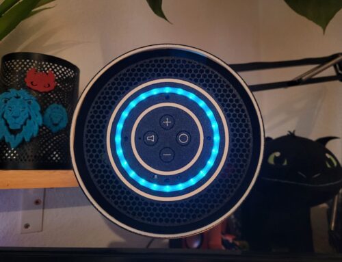
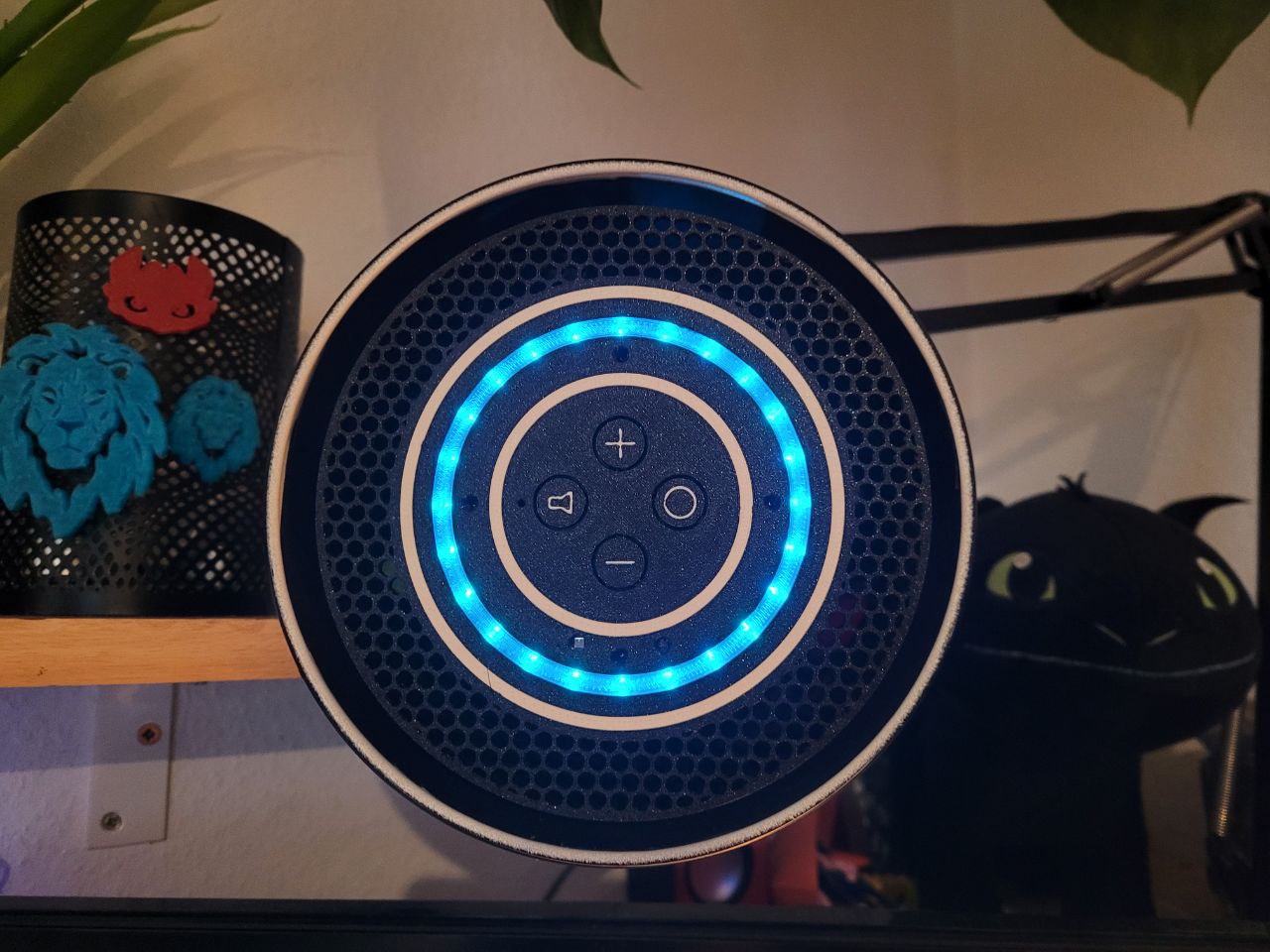
Control via Home Assistant on PC or Smartphone was easy. I planned to use mechanical switches to control the foot massager, but as the ESP32 already has pins to be used with capacitive touch buttons. I tried using the original touch buttons, after setting the thresholds it works great (see below)
The functions a little bit different than the original but fittet to my needs. If you press the air intensity button the pump will increase pressure until you press it again. A long click will open the valve and release the pressure. The power button will turn the motor on, long click will reverse the direction.
Calibration of Touch Buttons
The diagram shows the touch values of each button recorded via setup_mode: true. The buttons were activated once in sequence.
A slight crosstalk can be seen from the other keys, the threshold is set to a value between the activated buttons and the next crosstalk value.

Code ESPhome yaml
Options
- The h-bridge is optional. It controls speed and direction of the motor. If you just want full power in one direction you will not need it.
- All timings, massage patterns, button assignments can be altered to fit your needs
- The h-bridge has a second motor port. So one could connect the pump and run it slower… but what for?
- A different h-bridge could be used
- The relay for the motor is not needed but can be easily controlled to cut the power. However, three relays would be sufficient,
- Perhaps the voltage regulator of the h-bridge could be used to power the relay module and the ESP, so a seperate DC/DC converter would not be necessary.
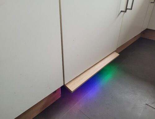
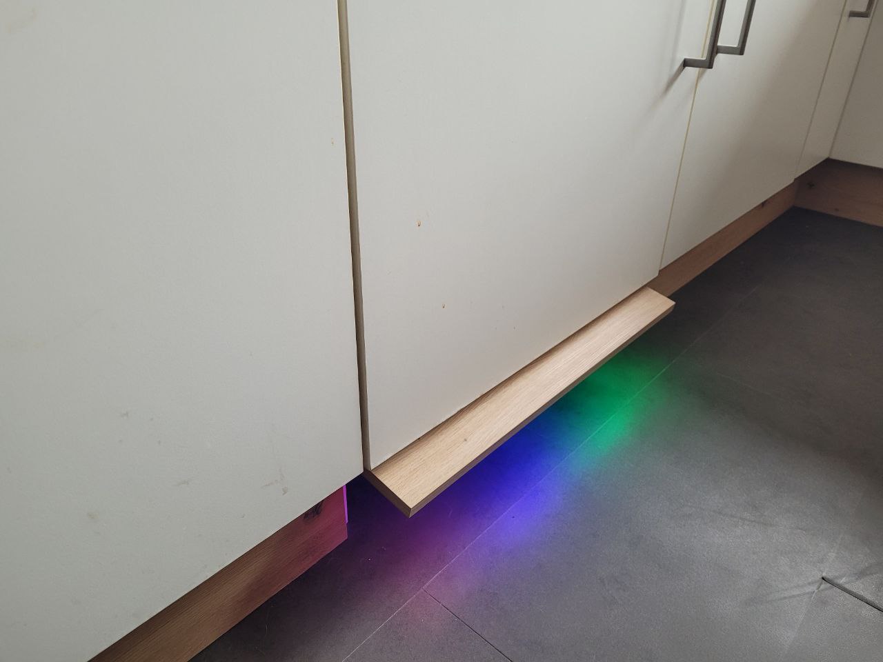
- LEDs (or a small display) could be added to display some states
- Instead of using global, the number component can be used
- Instead of using the if/for condition for the filter: – delayed_off: could be used


Had a similar problem with this exact model of foot massager. The machine did not respond to any of the buttons so was constantly turned on at one setting, could not change any settings at all. Got a new one on Amazon and swapped the unlabeled ICs near the middle of the PCBs, and the machine responded again. That was my clue, the unlabeled ICs seems to be the culprit if the machine fails. Could not find a replacement IC, I think it may be custom-made for this specific instance.
Did you end up returning the original? Did they notice? I have the same issue and am contemplating